COPYRIGHT WARNING:
All pictures and texts in this web page are the property of nomaallim.com. Any use of any part of those contents without the written consent of nomaallim.com shall be subject to legal procedures as per international and local laws in the concerned country. Using the name "nomaallim" or "nomaallim com" or "nomaallim.com" in the text describing the unauthorized copied content shall not constitute an exception and shall be sanctioned in accordance to the effective laws and proceedings.
All pictures and texts in this web page are the property of nomaallim.com. Any use of any part of those contents without the written consent of nomaallim.com shall be subject to legal procedures as per international and local laws in the concerned country. Using the name "nomaallim" or "nomaallim com" or "nomaallim.com" in the text describing the unauthorized copied content shall not constitute an exception and shall be sanctioned in accordance to the effective laws and proceedings.
BEFORE YOU START
|
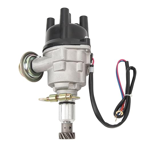
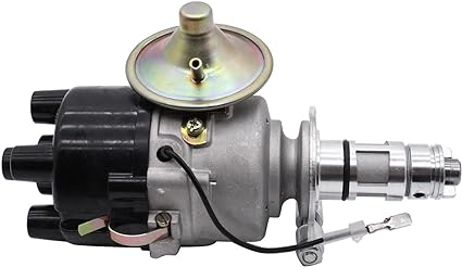
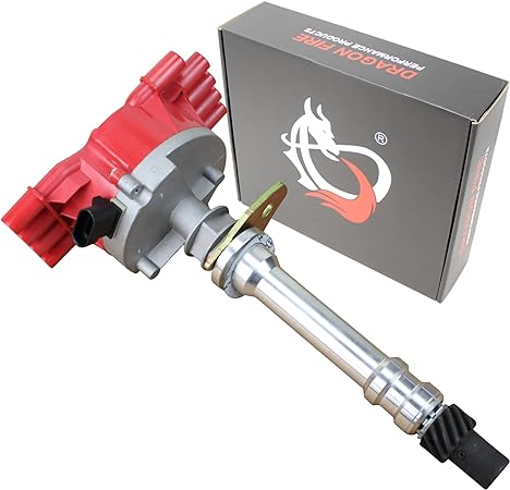
The below works concerned a "123 ignition" distributor that replaces the original Bosch distributor fitted on a Simca / Talbot / Matra / Poissy engine. The replacement method for different makes and versions remains highly similar.
|
DISCLAIMER:
Our pictorials are of informative nature and do illustrate works carried out by ourselves at our own premises for our own use and satisfaction.
Readers who envisage to carry out similar works inspired by the below method shall do this at their own risks and liability.
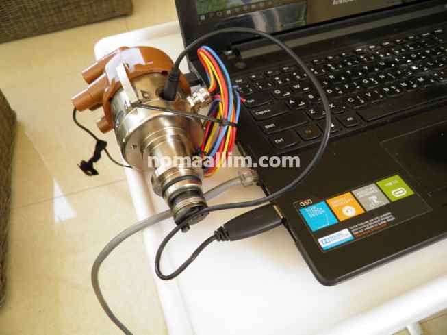
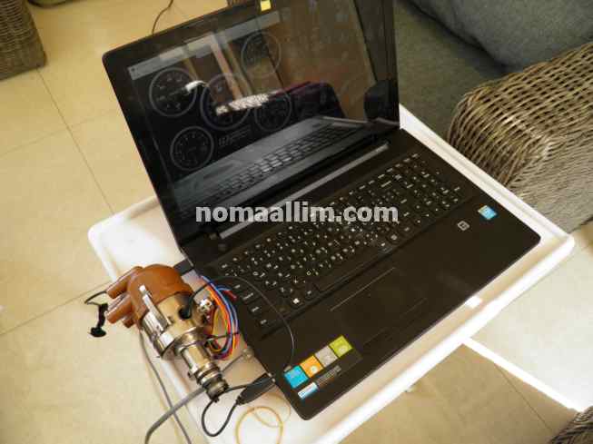
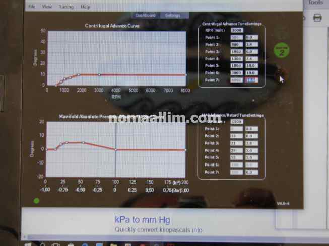
Step 1: program the centrifugal and manifold pressure curves into the USB replacement distributor for classic / old cars
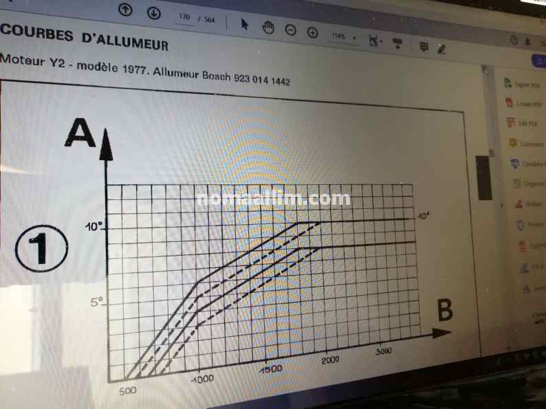
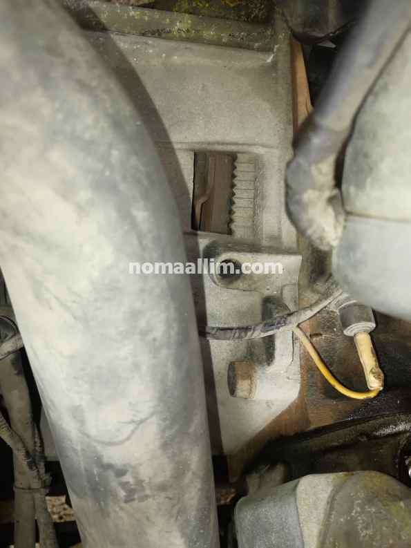
Start by finding the curves of the original distributor in your old or classic car.
Two curves are to be programmed in the new distributor, reason why you need to have them on-hand prior to proceeding with the very first step of the USB distributor preparation for installation:
Two curves are to be programmed in the new distributor, reason why you need to have them on-hand prior to proceeding with the very first step of the USB distributor preparation for installation:
- The centrifugal ignition timing advance expressed in degrees ahead of the top dead center. This ignition correction is due to the moving weights around the distributor shaft and their springs. The timing advance is set by the springs length.
- The other is about the same advance expressed as a function of the absolute inlet manifold pressure. Such correction results from the vacuum tube that links the carburetor base (or body) to the distributor pneumatic actuator (membrane).

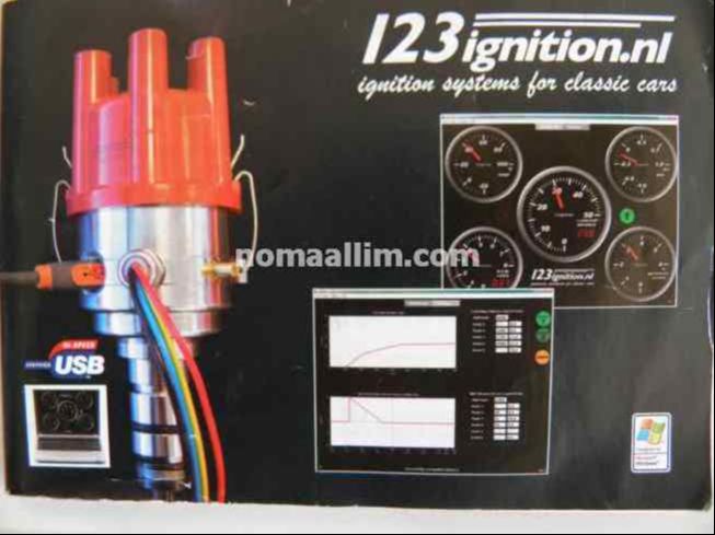
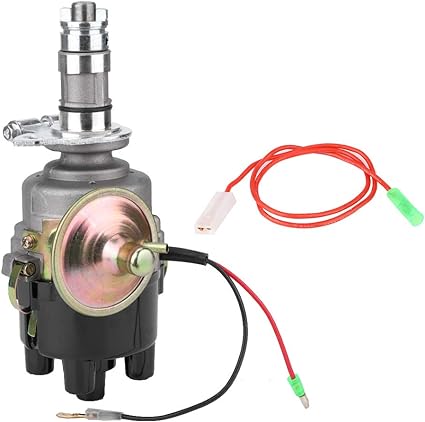
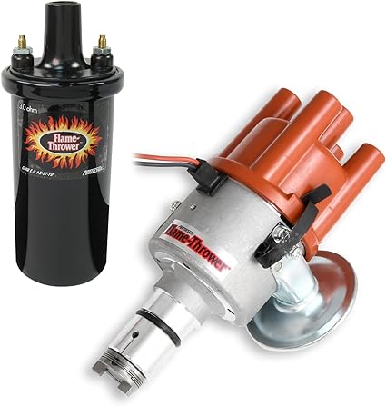
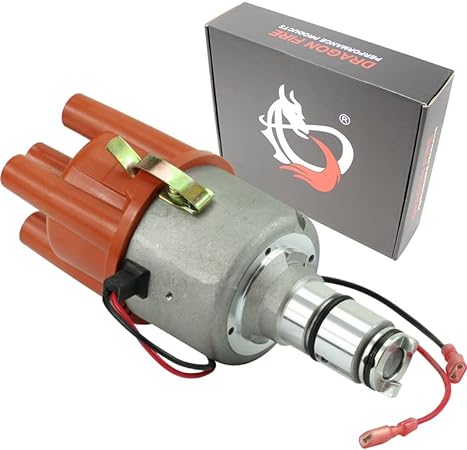
The replacement distributor offers the advantage of being:
- entirely electronic and therefore static, with no moving parts other than the rotating shaft
- programmable so you can enter your curves in it
- offering a different tuning option by programming a "Curve 2" to which the distributor shifts in case you connect a wire to a positive voltage (by adding a switch for example).
- having stainless steel body and highly splash proof construction as per modern times
|
|
|
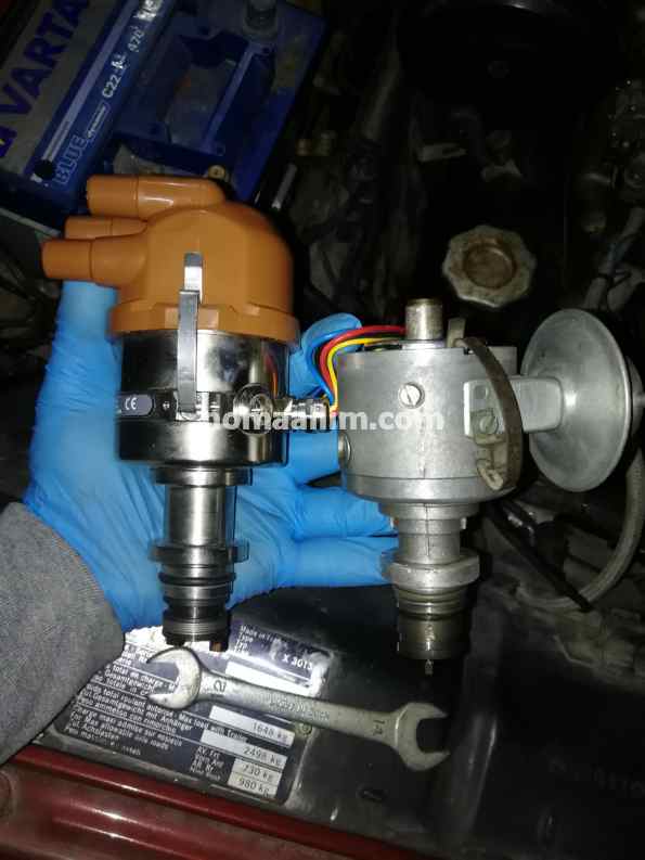
Step 2: verify and adjust the distributor rotor orientation
Having programmed your new distributor, you need first to make sure of its orientation compared to the old one as follows:
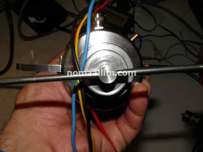
When the drive forks are in the same position, the rotors should be either parallel or perpendicular.
When the drive forks are in the same position, the rotors should be either parallel or perpendicular.
|
|
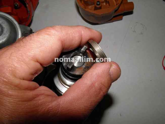
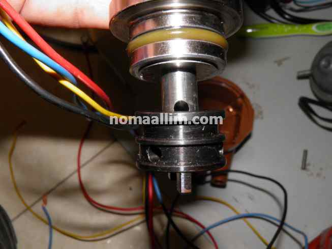
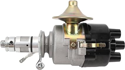
If this is not the case, remove the spring of the new distributor fork and take out its pin, i.e. the pin that holds the fork to the distributor shaft. You will notice it has two different holes for fitting the pin in, so rotate it in a manner to use the other fixing hole.
Refit the spring, compare the distributors and make sure of the orientation of the rotors.
Refit the spring, compare the distributors and make sure of the orientation of the rotors.
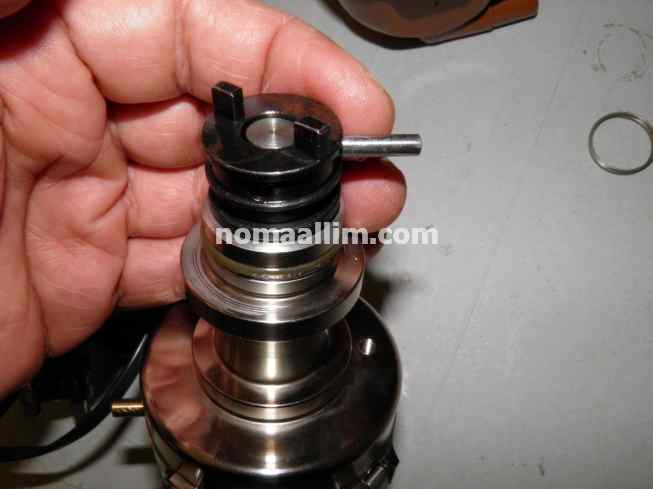
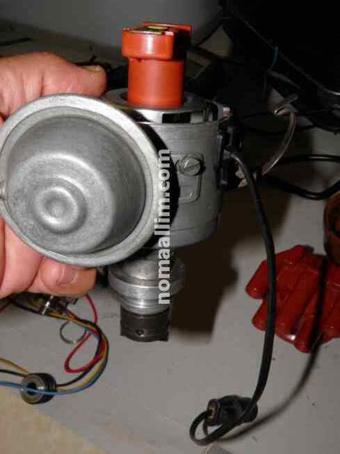
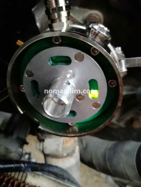
You can help yourself by introducing a screwdriver or pin remover in the distributor shaft whole then tilt the distributor upside down so you can compare the orientation of the rotor with the one of the hole in the shaft.
|
|
|
Step 3: block the USB distributor at the exact timing setting point.
Time now to fit the USB programmable distributor to the car.
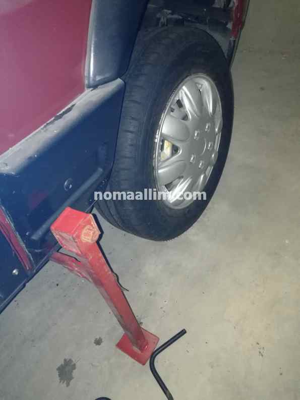
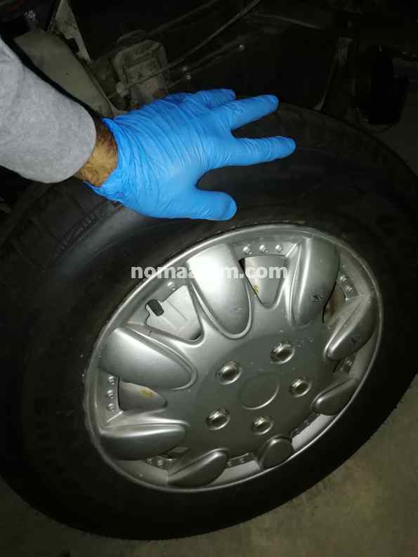
While the old distributor is fitted, lift your vehicle on one side of the drive train and rotate your wheel clockwise in order to:
While the old distributor is fitted, lift your vehicle on one side of the drive train and rotate your wheel clockwise in order to:
- Watch the distributor rotor and note if it rotates clockwise or anticlockwise
- Bring the rotor towards the contact of cylinder no 1 on the cap then set the engine at the exact timing point of cylinder no 1 i.e. when the timing mark on the flywheel matches the zero number of the timing advance scale. Do not set it to the normal advance point of your engine, simply on the zero.
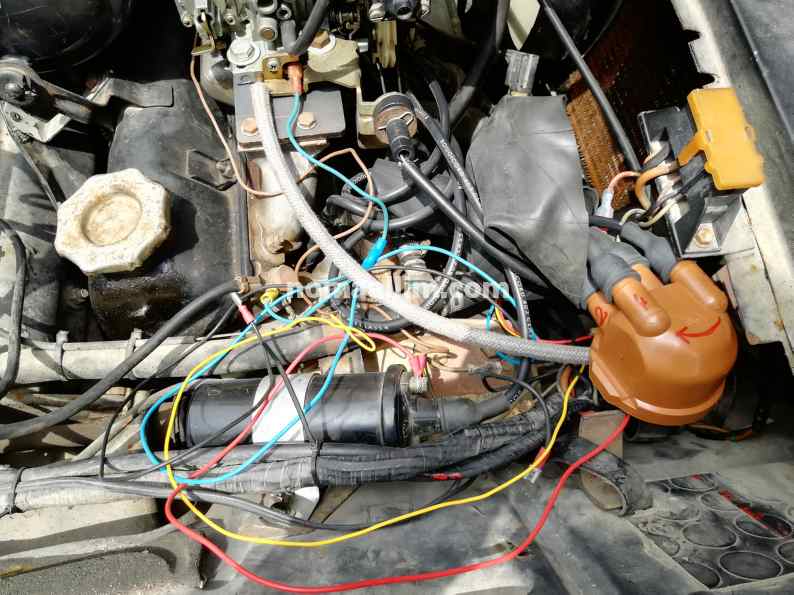
Fit your USB distributor in place of the old one and do the following:
- Rotate its body until the cap fits conveniently in the vehicle. You can rotate it 360 degrees, this has no importance.
- Wire the USB distributor to the +12 BAT and NEG terminals. Do not connect yet the signal wire coming from the distributor to the RUP terminal of your ignition coil.
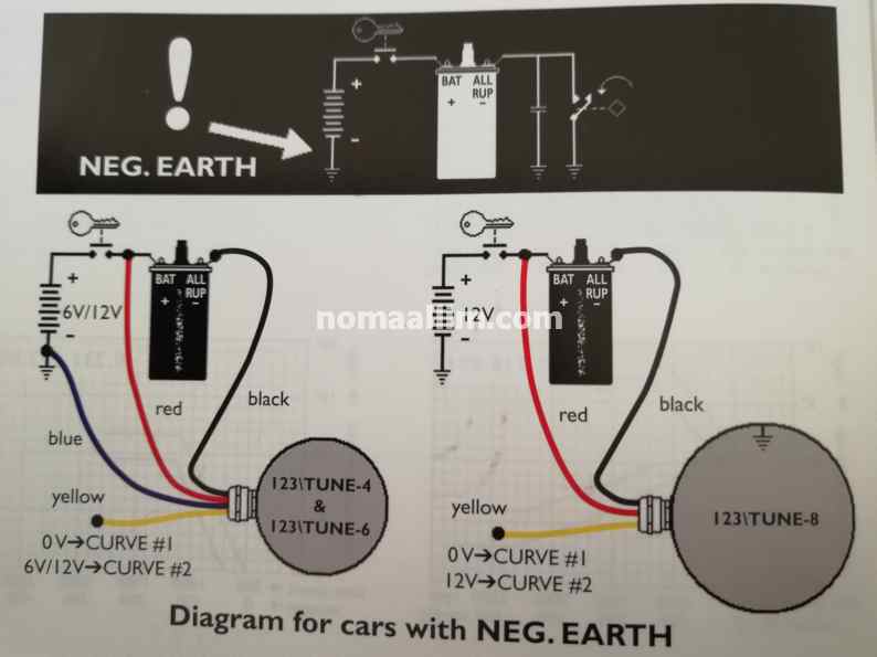
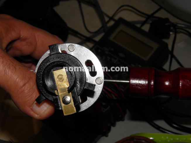
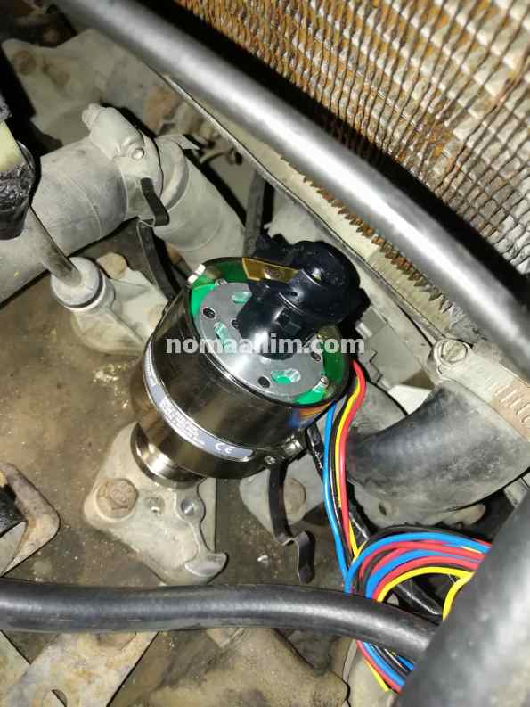
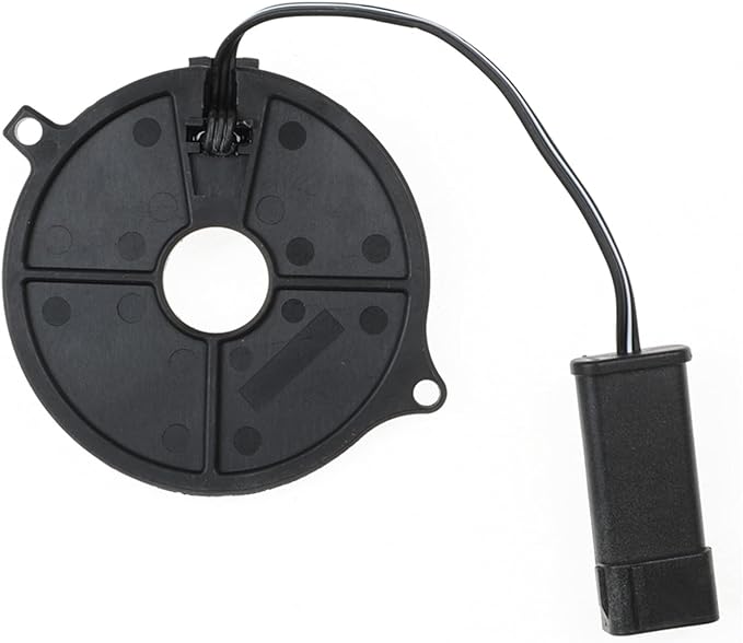
Now rotate the USB distributor body counterclockwise if your distributor rotor turns clockwise (and vice-versa) until the green LED goes on, then tighten the distributor holder in a manner to fix it in that exact position when the LED precisely goes ON.
To note that depending on the convenient orientation you had determined based on the distributor cap and ignition wires, the LED might not coincide with an opening as shown in the right picture, and could come ON while being beneath the disc. The setting is still valid but you need then to manage to see the LED's light which is not feasible if you're working outdoor under the sun.
To note that depending on the convenient orientation you had determined based on the distributor cap and ignition wires, the LED might not coincide with an opening as shown in the right picture, and could come ON while being beneath the disc. The setting is still valid but you need then to manage to see the LED's light which is not feasible if you're working outdoor under the sun.
|
|
|
|
|
Step 4: rewire the ignition wires to the new distributor cap in the adequate order
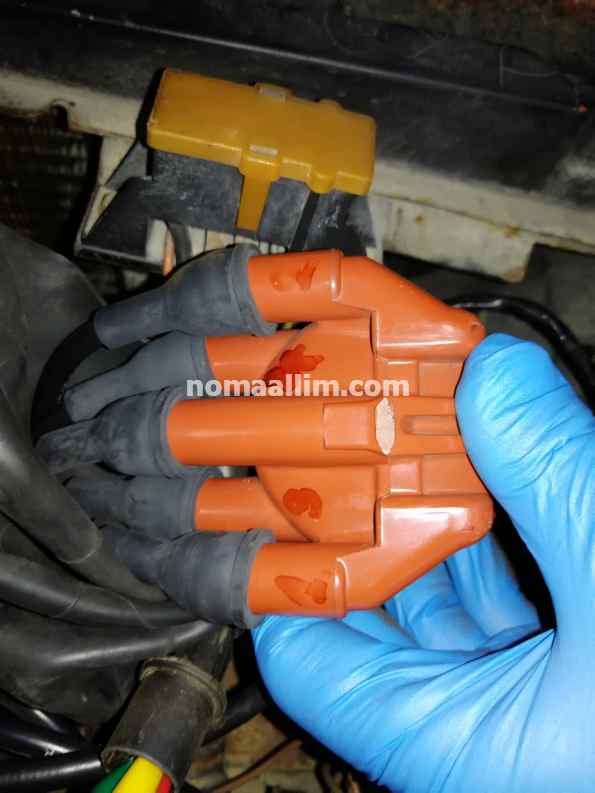
Now fit the distributor cap and check to which contact the rotor points. This is the cylinder no 1. No matter if it is not the same contact as in the old cap, it is important however that you connect the ignition wire of cylinder no 1 to that one and the others to the ignition order of your vehicle (mainly 1-3-4-2 on a 4-cylinder engine).
Connect the signal wire of the USB distributor to the RUP terminal of the ignition coil and keep all wires connected in a temporary manner for the time being.
Fit a strobe lamp to cylinder no 1 spark plug and start your engine.
Make sure the ignition timing is now coinciding with the normal value at idle as per your vehicle's instructions.
Proceed with the engine tuning and have fun properly routing the new distributor cables and the ignition wires as well. Fix all well with cable ties and keep them away from heat sources.
That's it, enjoy a reliable ride with this maintenance-free ignition system!

|
Buy your electronic dustributor at our partners' store:
|

|
|
|
|
|
|
|
|
|
|
See also...

|
|
|